Product Overview
Industrial pressure relief valves function as the final mechanical safety layer in pressurized systems. When system pressure exceeds predetermined safe limits, the valve opens dynamically to discharge media and prevent catastrophic vessel failure.
-
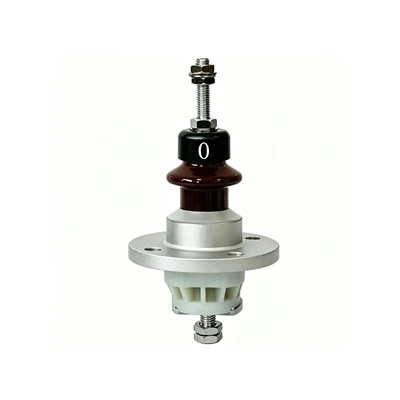
![Pressure Relief Valve for Oil-Filled Transformer]() Pressure Relief Valve for Oil-Filled Transformer• Nominal diameter: DN25–DN250view more
• Opening pressure: 30–150kPa (customizable)
• Operating temperature: -40℃~+85℃
• Action mode: automatic opening & reset
• Sealing performance: zero leakage under rated... -
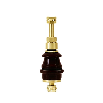
![Brass Transformer Pressure Relief Valve]() Brass Transformer Pressure Relief Valve• Nominal diameter: DN25–DN100view more
• Opening pressure: 30–150kPa (customizable)
• Working temperature: -40℃~+90℃
• Body material: brass
• Action mode: automatic opening and reset
• Sealing grade:... -
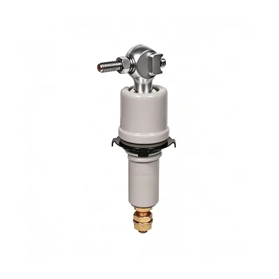
![Transformer Pressure Relief Valve with Alarm Contact]() Transformer Pressure Relief Valve with Alarm Contact• Nominal diameter: DN50–DN250view more
• Opening pressure: 35–150kPa (customizable)
• Operating temperature: -40℃~+85℃
• Action mode: automatic opening & reset -
![Mechanical Pressure Relief Valve for Transformer]() Mechanical Pressure Relief Valve for Transformer• Nominal diameter: DN40–DN200view more
• Opening pressure: 30–150kPa (customizable)
• Working temperature: -40℃~+90℃
• Action mode: automatic opening and reset -
![Diaphragm Type Transformer Pressure Relief Valve]() Diaphragm Type Transformer Pressure Relief Valve• Nominal diameter: DN50-DN250view more
• Opening pressure: 35-138kPa (customizable)
• Operating temperature: -40℃~+85℃
• Action response: ≤10ms
• Sealing grade: IP67 -
![Spring-Loaded Transformer Pressure Relief Valve]() Spring-Loaded Transformer Pressure Relief Valve• Model: YSF Seriesview more
• Nominal Diameter: DN50, DN80, DN130
• Opening Pressure: 35kPa / 50kPa / 55kPa (customizable)
• Closing Pressure: 13kPa / 25kPa / 27kPa
• Operating Medium: Transformer Oil -
![Pressure Relief Valve for Transformer]() Pressure Relief Valve for Transformer• Model:YSF seriesview more
• Caliber:Φ50/Φ80/Φ130mm
• Opening pressure:35kPa / 50kPa / 55kPa
• Closing pressure:13kPa / 25kPa / 27kPa
• Working medium:transformer oil -
![Pressure Relief Transformer]() Pressure Relief Transformer• Operating Pressure: 35–70kPa (oil‑immersed) / 7–14kPa (dry-type)view more
• Reset Pressure: ≤ 50% of operating pressure
• Response Time: ≤ 2ms
• Operating Temperature: -40℃ ~ +100℃
• Protection Class: IP65


Product Types & Working Principle
Direct Spring-Loaded Valves
System pressure acts directly underneath the disc against a calibrated spring force. When force exceeds spring tension, the disc lifts instantly (pop action) or proportionally (proportional action). Utilized in standard liquid and gas applications.
Pilot-Operated Valves
Consist of a main valve and a pilot control valve. System pressure maintains the main valve disc on its seat with a high sealing force up to the set point. Ideal for high-pressure, high-capacity systems operating close to the maximum allowable working pressure (MAWP).
Construction & Materials
Bodies cast in ASTM A216 WCB (carbon steel) or ASTM A351 CF8M (316 stainless steel). Trims hardened with Stellite overlay on seat interfaces to resist wire-drawing and particulate erosion. Bellows-balanced configurations available to negate the effect of backpressure.

Blowdown Adjustment: Adjustable nozzle rings control blowdown tolerances between 5% and 7% of the set pressure, minimizing media loss during venting cycles.
Metal-to-Metal Seating: Precision-lapped disc and seat geometries meet strict leakage rate standards without relying on soft elastomeric inserts that degrade under thermal cycling.
Guided Motion: Top and bottom guided stems prevent side-thrust friction and ensure repeatable pop-action dynamics across 10,000+ actuation cycles.
Technical Specifications
|
Specification Parameter |
Standard Range / Metric |
|
Size Range |
NPS 1/2 inch to 12 inch (DN15 to DN300) |
|
Pressure Class |
ASME Class 150 to 2500 (PN16 to PN420) |
|
Set Pressure |
0.1 MPa to 42.0 MPa |
|
Operating Temp |
-196°C to +550°C |
|
Body Materials |
WCB, CF8M, CF3M, Hastelloy C276, Monel |
|
Design Standards |
API 526, ASME Section VIII, ISO 4126, PED Directives |
|
Testing Standards |
API 527, API 576 |
Applications
Steam Generation
Boiler drum overpressure protection, superheater loops, and turbine extraction lines operating up to 540°C.
Petrochemical Refining
Distillation column overhead protection, hydrocracker reactor effluent lines, and high-temperature flare headers.
Cryogenic Storage
Liquid nitrogen and LNG storage tank boil-off management utilizing low-temperature austenitic stainless steel bodies.
Manufacturing & Quality Control
Machining: CNC horizontal boring centers maintain coaxiality tolerances within +/- 0.01 mm between the guide bushing and seat bore to prevent stem binding.
Seat Lapping: Optical flat verification ensures 3-band monochromatic light interference patterns on metal seats, guaranteeing bubble-tight shutoff per standard leakage criteria.
Testing Facilities: Computerized nitrogen and steam test benches verify set pressure accuracy, reseating pressure, and leakage rates. Each valve receives an individual calibration certificate traceable to serial numbers.
Certifications: Pressure equipment directive compliance, quality management system integration, and material boundary integrity standards.
Customization
Special Trim Overlays
Stellite Gr. 6 weld overlays applied via PTA (Plasma Transferred Arc) welding for abrasive slurries or high-velocity steam service.
Corrosion Allowance
Thicker body walls or solid alloy construction (Inconel 625, Titanium Gr. 2) specified for sour gas environments.
Accessory Integration
Proximity switches for open-position feedback, rupture disc assemblies installed upstream, and special flange facings (RTJ, Tongue and Groove).
Hebei Anmei Electrical Equipment Co., Ltd. is one of the most professional pressure relief valve manufacturers and suppliers in China, specialized in providing high quality products and service. Please feel free to buy customized pressure relief valve made in China here from our factory. Contact us for quotation.
flanged hydraulic relief valve, industrial system relief valve, transformer utility pressure control valve